


Statics
Forces, moments and equilibrium: vectors, free-body diagrams, rigid bodies in 2D and 3D, trusses, frames and machines, centroids and fluid pressure, shear and bending-moment diagrams, cables and friction, with six labs. Free, self-paced, and tied to wind power, bridges, dams and the space station.
Courses › ENGR 211
About this course
This is a free self-study course outline written by Saving Planets. It is not a university course, it carries no academic credit, and no school is involved.
Its scope follows a one-semester sophomore engineering statics course. It is modeled on the topics and depth of MIT 2.001 (the statics half of Mechanics and Materials I, on MIT OpenCourseWare), Purdue ME 270 and Georgia Tech COE 2001, and on the free open textbook Engineering Statics: Open and Interactive and OpenStax University Physics Volume 1 (Chapter 12), which we link throughout. None of those authors or schools endorses this page.
What we add: every unit ties to real clean-energy, infrastructure or space work with a cited public source (wind turbines, floating offshore wind, bridges, Hoover Dam, the space station, landslides, building materials), every number on the page is re-computed by a checking script before it goes live, and every lab has a free simulation or a cheap home version.
Work through it in order. Each unit has goals, key ideas, equations, step-by-step examples, practice with full answers, common mistakes, flashcards and a quiz. Your progress is saved only in this browser.
How this course helps save the planet
Clean energy and resilient infrastructure stand on statics. A wind turbine tower must resist the overturning moment of the wind on its rotor, a floating offshore platform is held in place by mooring lines in balance, a dam turns water pressure into forces its concrete can carry, and every bridge is checked by summing forces and moments.
Statics is also how we build lighter and waste less: a well-designed truss or frame uses less steel, concrete and wood for the same job, and structures that last longer keep materials out of landfills. Each unit ends with a short, sourced section. Values that are not from a source are labeled as sample values.
Before you start
Prerequisites
- Physics I: forces, Newton’s laws, torque and free-body diagrams.
- Calculus I and II: derivatives and integrals (for distributed loads, centroids and moment diagrams).
- Vectors: components, dot and cross products (reviewed in Unit 1).
- Calculus III and Linear Algebra help with 3D problems but are not required.
How to study
- Draw a free-body diagram first, every time. Most statics mistakes are a missing or extra force on the diagram.
- Pick axes and a moment point that remove as many unknowns as possible.
- Solve with symbols first, then put in numbers in SI units, and check units and signs at the end.
- Count unknowns and independent equations before solving, so you know whether the problem can be solved by statics alone.
- Check the answer with an equation you did not use (for example, a second moment point).
- Do every practice problem on paper before opening the answer, and retake the quizzes a few days later.
Lab equipment (for the wet labs)
- A computer or tablet for the free PhET simulations (they run in a browser).
- A digital luggage scale or a kitchen scale, string, a few known masses (water bottles or bags of rice with the mass on the label work).
- A 30 cm ruler, a pencil, coins or washers, and a smartphone protractor or inclinometer app.
- Craft sticks or stiff card, a glue gun or white glue, and pins.
- A sheet of corrugated cardboard, scissors, a pushpin and a thread with a small weight (a plumb line).
- A hardcover book, a small box, and a smooth mug or round post for the rope-friction test.
Suggested 15-week schedule
About 6 to 9 hours a week: reading, practice problems and, in lab weeks, the lab.
| Week | Unit | Topics | Reading |
|---|---|---|---|
| 1 | Forces and Vectors in 2D and 3D | Units, forces as vectors, 2D components and resultants | Engineering Statics Ch. 1–2 |
| 2 | Forces and Vectors in 2D and 3D | 3D vectors, position and unit vectors, dot product; Lab A | Ch. 2 |
| 3 | Equilibrium of a Particle | Free-body diagrams, particle equilibrium in 2D and 3D, springs; Lab B | Ch. 3; OpenStax UP1 12.1 |
| 4 | Moments, Couples and Equivalent Systems | Moments in 2D and 3D, cross product, Varignon | Ch. 4.1–4.4 |
| 5 | Moments, Couples and Equivalent Systems | Moment about an axis, couples, equivalent systems, distributed loads; Lab C | Ch. 4.5–4.8 |
| 6 | Rigid-Body Equilibrium in 2D | Supports, 2D rigid-body equilibrium, determinacy | Ch. 5.1–5.4; UP1 12.2 |
| 7 | Rigid-Body Equilibrium in 3D | 3D rigid-body equilibrium; midterm practice | Ch. 5.5–5.6 |
| 8 | Trusses: Method of Joints and Method of Sections | Trusses: joints, zero-force members, sections; Lab D | Ch. 6.1–6.4 |
| 9 | Frames and Machines | Frames and machines | Ch. 6.5–6.6 |
| 10 | Centroids, Distributed Loads, Fluid Pressure and Area Moments of Inertia | Centroids and centers of gravity, composite parts; Lab E | Ch. 7 |
| 11 | Centroids, Distributed Loads, Fluid Pressure and Area Moments of Inertia | Distributed loads, fluid pressure, area moments of inertia | Ch. 7, Ch. 10; UP1 14.1 |
| 12 | Internal Forces: Shear and Bending-Moment Diagrams, and Cables | Internal forces, shear and moment diagrams | Ch. 8.1–8.2 |
| 13 | Internal Forces: Shear and Bending-Moment Diagrams, and Cables | Load–shear–moment relations, cables | Ch. 8.3 |
| 14 | Friction | Dry friction, wedges, ladders, belt friction; Lab F | Ch. 9; UP1 6.2 |
| 15 | Review | Review and final practice set | All units |
Your progress
Tick units and labs as you finish them, and take the quizzes. Progress and quiz scores are saved only in this browser, never sent to us.
Turn on JavaScript to track progress.
Unit 1 · Weeks 1–2
Forces and Vectors in 2D and 3D
What statics is, units, forces as vectors, components, resultants, unit vectors and position vectors in 3D, and the dot product for angles and projections.
Learning objectives
By the end of this unit you can:
- Resolve a force into components in 2D and 3D.
- Add forces to find a resultant and its direction.
- Write a force along a line from two points.
- Use the dot product to find angles and projections.
Key concepts
- Statics studies bodies whose acceleration is zero, so the forces on them balance: ΣF = 0 and ΣM = 0.
- A force has magnitude, direction and a point (or line) of action. In SI it is measured in newtons; 1 kg weighs 9.81 N.
- In 2D, a force F at angle θ from the x axis has components F cos θ and F sin θ. Resultants add component by component.
- In 3D, write F = F û, where û is a unit vector. Along a line from A to B, û = (r_B − r_A)/|r_B − r_A|.
- The dot product A·B = |A||B| cos θ gives the angle between two vectors and the component of a force along any line.
Key equations
Worked examples, step by step
Example 1.1 A 500 N force acts at 30° above the +x axis. Find its components.
Show the steps
- F_x = 500 cos 30° = 433 N.
- F_y = 500 sin 30° = 250 N.
Answer: F = (433, 250) N.
Example 1.2 Add F₁ = 300 N along +x and F₂ = 400 N at 120° from +x.
Show the steps
- F₂ = (400 cos 120°, 400 sin 120°) = (−200, 346.4) N.
- R = (100, 346.4) N, so |R| = √(100² + 346.4²).
- θ = tan⁻¹(346.4/100).
Answer: 360.6 N at 73.9° from +x.
Example 1.3 A cable pulls with 1.2 kN from A(0, 0, 0) toward B(2, 3, 6) m. Write the force as a vector.
Show the steps
- r_AB = (2, 3, 6) m, length √(4 + 9 + 36) = 7 m.
- û = (2/7, 3/7, 6/7).
- F = 1200 û.
Answer: F = (343, 514, 1029) N.
Practice problems
Work each on paper first, then check.
Find the angle between A = (3, 4, 0) and B = (4, 0, 3).
Show answer
A·B = 12, |A| = |B| = 5, cos θ = 0.48, θ = 61.3°.
Find the component of F = (100, 200, −50) N along û = (0.6, 0.8, 0).
Show answer
F·û = 60 + 160 = 220 N.
Find the direction angles of F = (200, −300, 600) N.
Show answer
|F| = 700 N; α = cos⁻¹(2/7) = 73.4°, β = cos⁻¹(−3/7) = 115.4°, γ = cos⁻¹(6/7) = 31.0°.
Sample values: a 50 kN force on a structure acts 20° above horizontal. Find its horizontal and vertical parts.
Show answer
F_x = 50 cos 20° = 47.0 kN; F_y = 50 sin 20° = 17.1 kN.
Common misconceptions
Myth: Forces add like numbers: 300 N + 400 N = 700 N.
Actually: They add as vectors; 300 N and 400 N at right angles give 500 N.
Myth: A unit vector has units of newtons.
Actually: A unit vector is dimensionless with length 1; the magnitude carries the units.
Myth: Mass and weight are the same thing.
Actually: Mass is in kg; weight is a force, mg, in newtons.
Flashcards
Statics
Bodies at rest or constant velocity: ΣF = 0, ΣM = 0.
Components
F_x = F cos θ, F_y = F sin θ.
Unit vector
û = r/|r|, length 1.
Force along a line
F = F (r_B − r_A)/|r_B − r_A|.
Dot product
A·B = |A||B| cos θ.
Weight
W = mg, 9.81 N per kg.
Self-check quiz
How this helps save the planet
A wind turbine blade is a lesson in force vectors. The U.S. Department of Energy explains that wind flowing across a blade creates both lift and drag, and that the lift is stronger than the drag, which makes the rotor spin. Engineers resolve those forces into components along and across the rotor to size the blades, the hub and the tower.
On Saving Planets: Physics I
Sources: U.S. DOE: How do wind turbines work? · Engineering Statics, Chapter 2: Forces and other vectors
Free learning resources
- Engineering Statics, Ch. 2 Forces and other vectors: Free textbook chapter.
- OpenStax UP1, 2.1 Scalars and vectors: Vector basics.
- PhET: Vector Addition: Interactive.
Unit 2 · Week 3
Equilibrium of a Particle
Free-body diagrams, equilibrium of concurrent forces in 2D and 3D, cables, pulleys and springs.
Learning objectives
By the end of this unit you can:
- Draw a complete free-body diagram of a particle.
- Solve 2D equilibrium for two unknowns.
- Solve 3D equilibrium with cable forces written as vectors.
- Model springs with F = kδ.
Key concepts
- A particle is a body small enough that all forces act at one point, so only ΣF = 0 matters (two equations in 2D, three in 3D).
- A free-body diagram (FBD) isolates the body and shows every external force on it, with known directions and labeled unknowns.
- A cable or rope can only pull, along its own line. Over an ideal pulley the tension is the same on both sides.
- A linear spring pulls or pushes with F = kδ, where δ is the change from its unstretched length.
- If you get a negative tension, the assumed direction was wrong; a cable cannot push, so the setup must change.
Key equations
Worked examples, step by step
Example 2.1 A 100 kg mass hangs from two cables, each 30° above horizontal. Find the tension.
Show the steps
- W = 100 × 9.81 = 981 N.
- Vertical: 2T sin 30° = 981.
Answer: T = 981 N in each cable.
Example 2.2 A 50 kg mass hangs from cable B at 30° and cable C at 45° above horizontal, on opposite sides. Find both tensions.
Show the steps
- W = 490.5 N.
- Horizontal: T_B cos 30° = T_C cos 45°.
- Vertical: T_B sin 30° + T_C sin 45° = 490.5, so T_B (0.5 + 0.866) = 490.5.
Answer: T_B = 359.1 N, T_C = 439.8 N.
Example 2.3 A spring with k = 2000 N/m holds a 20 kg mass at rest. How far does it stretch?
Show the steps
- kδ = mg = 196.2 N.
- δ = 196.2/2000.
Answer: 0.0981 m (98.1 mm).
Practice problems
Work each on paper first, then check.
A 10 kg block rests on a smooth 25° incline, held by a cable parallel to the slope. Find the tension and normal force.
Show answer
T = mg sin 25° = 41.5 N; N = mg cos 25° = 88.9 N.
A 600 N load hangs from three cables to points (2, 0, 4), (−1, 1.732, 4) and (−1, −1.732, 4) m. Find each tension.
Show answer
Each cable is √20 = 4.47 m long with vertical share 4/4.47 = 0.894; by symmetry 3T(0.894) = 600, so T = 223.6 N.
Two slings, each 60° above horizontal, lift a 2,000 kg load. Find the sling tension.
Show answer
T = 19,620/(2 sin 60°) = 11,327 N ≈ 11.3 kN.
Why do sling tensions grow as the sling angle gets flatter?
Show answer
T = W/(2 sin θ); as θ → 0, sin θ → 0 and T grows without limit.
Common misconceptions
Myth: The tension in a cable equals the weight it holds.
Actually: Only when the cable is vertical; at an angle it must be larger.
Myth: Forces from the body on its supports go on its FBD.
Actually: Only forces acting on the body go on its FBD.
Myth: A heavier object on a pulley rope makes tension different on each side.
Actually: An ideal, frictionless pulley keeps the tension the same on both sides.
Flashcards
Particle
All forces meet at one point; only ΣF = 0.
Free-body diagram
The isolated body with every external force on it.
Cable
Pulls along its own line only.
Ideal pulley
Same tension on both sides.
Spring
F = kδ.
Negative answer
The assumed direction was wrong.
Self-check quiz
How this helps save the planet
The U.S. Department of Energy notes that much offshore wind energy potential exists over waters too deep for fixed-bottom foundations secured to the sea floor, so turbines there need floating platforms. A floating platform stays in place because its mooring lines, buoyancy and weight balance, which is particle and rigid-body equilibrium on a giant scale.
On Saving Planets: Physics I
Sources: U.S. DOE: Floating Offshore Wind Shot · Engineering Statics, Chapter 3: Equilibrium of particles
Free learning resources
- Engineering Statics, Ch. 3 Equilibrium of particles: Free textbook chapter.
- OpenStax UP1, 12.1 Conditions for static equilibrium: Physics view.
- PhET: Forces and Motion: Basics: Balanced forces.
- PhET: Hooke’s Law: Springs.
Unit 3 · Weeks 4–5
Moments, Couples and Equivalent Systems
Moment of a force in 2D and 3D, the cross product, Varignon’s theorem, moment about an axis, couples, equivalent force systems, and resultants of distributed loads.
Learning objectives
By the end of this unit you can:
- Find the moment of a force about a point in 2D (scalar) and 3D (cross product).
- Find the moment of a force about an axis.
- Work with couples and replace a force system by an equivalent force and couple.
- Replace a distributed load by its resultant.
Key concepts
- The moment of a force about a point O is M_O = r × F, where r runs from O to any point on the force’s line. In 2D its size is F times the perpendicular distance d.
- Varignon’s theorem: the moment of a force equals the sum of the moments of its components, so M_z = xF_y − yF_x.
- The moment about an axis is the component of M_O along that axis: M_a = û_a·(r × F).
- A couple is two equal, opposite, parallel forces. Its moment Fd is the same about every point, so it is a free vector.
- Any force system can be replaced by one force and one couple at any point. A distributed load w(x) is equivalent to a force equal to its area, acting at its centroid.
Key equations
Worked examples, step by step
Example 3.1 A 200 N pull acts at the end of a 0.40 m wrench, at 60° to the handle. Find the moment about the bolt.
Show the steps
- Perpendicular part of the force: 200 sin 60°.
- M = 0.40 × 200 sin 60°.
Answer: 69.3 N·m.
Example 3.2 Find M_O for r = (2, 1, 0) m and F = (0, 0, 500) N.
Show the steps
- r × F = (1 × 500 − 0, 0 − 2 × 500, 0).
- |M| = √(500² + 1000²).
Answer: M_O = (500, −1000, 0) N·m, size 1118 N·m.
Example 3.3 A beam carries a uniform 4 kN/m over 5 m and, elsewhere, a triangular load rising from 0 to 6 kN/m over 3 m. Find each resultant.
Show the steps
- Uniform: area 4 × 5 at the middle.
- Triangle: area ½ × 6 × 3 at two-thirds of the way from the zero end.
Answer: 20 kN at 2.5 m; 9 kN at 2 m from the zero end.
Practice problems
Work each on paper first, then check.
Two 150 N forces form a couple with arms 0.25 m apart. Find the couple moment.
Show answer
M = Fd = 37.5 N·m, the same about any point.
F = (300, 400) N acts at (2, 1.5) m. Find M about the origin.
Show answer
M_z = xF_y − yF_x = 800 − 450 = 350 N·m, counterclockwise.
Sample values: wind pushes a turbine rotor with 400 kN at a hub 100 m above the ground. Find the overturning moment at the base.
Show answer
M = 400 kN × 100 m = 40 MN·m (sample values).
Replace 2 kN at x = 3 m and 4 kN at x = 6 m (both downward) by one force.
Show answer
F_R = 6 kN at x̄ = (2 × 3 + 4 × 6)/6 = 5 m.
Common misconceptions
Myth: Moment = force × distance to the point of application.
Actually: Use the perpendicular distance to the line of action.
Myth: A couple tends to move a body sideways.
Actually: A couple has zero net force; it only rotates.
Myth: r × F = F × r.
Actually: The cross product changes sign when the order flips.
Flashcards
Moment
M_O = r × F; size Fd.
Varignon
Moment of a force = sum of the moments of its components.
Moment about an axis
M_a = û·(r × F).
Couple
Equal, opposite, parallel forces; moment Fd everywhere.
Equivalent system
One force plus one couple at any point.
Distributed load
Resultant = area, acting at the centroid.
Self-check quiz
How this helps save the planet
Tall towers mean big moments. The U.S. Department of Energy says offshore wind turbines tend to be massive and taller than the Statue of Liberty, and that larger turbines are more cost-effective. The wind’s push on a rotor high above the base makes a large overturning moment, and the tower, foundation or floating platform must supply an equal and opposite moment. A moment calculation like the sample one in the practice problems is where every tower design starts.
On Saving Planets: Physics I
Sources: U.S. DOE: How do wind turbines work? · Engineering Statics, Chapter 4: Moments and static equivalence
Free learning resources
- Engineering Statics, Ch. 4 Moments and static equivalence: Free textbook chapter.
- OpenStax UP1, 10.6 Torque: Moments in physics.
- PhET: Balancing Act: Interactive.
Unit 4 · Week 6
Rigid-Body Equilibrium in 2D
Supports and their reactions, free-body diagrams of rigid bodies, the three planar equilibrium equations, two- and three-force members, and statical determinacy.
Learning objectives
By the end of this unit you can:
- Replace each support (pin, roller, fixed) by the right reactions.
- Solve for support reactions with ΣF_x = ΣF_y = ΣM = 0.
- Recognize two-force members.
- Decide whether a body is statically determinate, indeterminate or improperly supported.
Key concepts
- A rigid body needs both ΣF = 0 and ΣM = 0. In 2D that is three equations: ΣF_x = 0, ΣF_y = 0 and ΣM_A = 0 about any point A.
- Supports: a roller gives one force normal to its surface, a pin gives two force components, and a fixed support gives two forces and a couple.
- Take moments about the point where the most unknowns meet; that often gives one unknown per equation.
- A two-force member (forces at only two points, no moment) carries equal and opposite forces along the line joining those points.
- With more unknown reactions than equations a body is statically indeterminate; with reactions all parallel or all through one point it is improperly constrained.
Key equations
Worked examples, step by step
Example 4.1 A 6 m simply supported beam (pin at A, roller at B) carries 12 kN at 2 m from A. Find the reactions.
Show the steps
- ΣM_A = 0: 6R_B = 12 × 2.
- ΣF_y = 0: R_A = 12 − R_B.
Answer: R_B = 4 kN, R_A = 8 kN.
Example 4.2 A 3 m cantilever carries 2 kN/m along its length plus 5 kN at the tip. Find the wall reactions.
Show the steps
- Distributed resultant 6 kN at 1.5 m.
- V = 6 + 5; M = 6 × 1.5 + 5 × 3.
Answer: V = 11 kN up, M = 24 kN·m at the wall.
Example 4.3 An 8 m beam has a pin at x = 0, a roller at x = 6 m, and a uniform 3 kN/m over the whole length. Find the reactions.
Show the steps
- Resultant 24 kN at x = 4 m.
- ΣM_A: 6R_B = 24 × 4.
- R_A = 24 − R_B.
Answer: R_B = 16 kN, R_A = 8 kN.
Practice problems
Work each on paper first, then check.
A 4 m horizontal boom is pinned at a wall; a cable from its tip to the wall makes 30° with the boom. A 500 kg load hangs at the tip. Find the cable tension and pin reactions (ignore the boom’s weight).
Show answer
ΣM_pin: T sin 30° × 4 = 4905 × 4, T = 9810 N; A_x = T cos 30° = 8496 N; A_y = 4905 − 4905 = 0.
A beam has a pin and two rollers. Is it determinate?
Show answer
Four unknown reactions, three equations: indeterminate to the first degree.
Sample values: a 10 m bridge span carries an 80 kN truck axle group 4 m from support A. Find the reactions.
Show answer
R_B = 80 × 4/10 = 32 kN; R_A = 48 kN (sample values).
Why is a beam on three rollers (all vertical) not safe?
Show answer
Nothing resists horizontal force: it is improperly constrained even though it has three reactions.
Common misconceptions
Myth: A pin support gives a moment.
Actually: A pin lets the body rotate; only a fixed support gives a couple.
Myth: Always take moments about the center.
Actually: Pick the point that removes the most unknowns.
Myth: Three reactions always mean determinate.
Actually: Not if they are all parallel or all meet at one point.
Flashcards
Roller
One reaction, normal to the surface.
Pin
Two force reactions.
Fixed support
Two forces and a couple (2D).
Two-force member
Equal, opposite forces along the line between its ends.
Statically indeterminate
More unknowns than equilibrium equations.
Improper constraint
Reactions all parallel or concurrent.
Self-check quiz
How this helps save the planet
Every bridge rating starts with support reactions. ASCE’s Report Card counts 623,218 U.S. bridges, of which 6.8% are in poor condition and 63,085 were posted for load in 2024, meaning they limit the weight of vehicles allowed to cross. Load posting and repair decisions rest on the same equilibrium equations as this unit; keeping existing bridges in service longer also saves the concrete and steel a replacement would need.
On Saving Planets: Solutions
Sources: ASCE Report Card for America’s Infrastructure: Bridges · Engineering Statics, Chapter 5: Rigid body equilibrium
Free learning resources
- Engineering Statics, Ch. 5 Rigid body equilibrium: Free textbook chapter.
- OpenStax UP1, 12.2 Examples of static equilibrium: Worked physics examples.
- PhET: Balancing Act: Interactive.
Unit 5 · Week 7
Rigid-Body Equilibrium in 3D
Supports in 3D (ball and socket, hinge, bearing, fixed), six equilibrium equations, moments about axes to isolate unknowns, and determinacy in 3D.
Learning objectives
By the end of this unit you can:
- Model 3D supports with the right reactions.
- Write and solve the six equations of 3D equilibrium.
- Use moments about well-chosen axes to find one unknown at a time.
- Count unknowns to judge 3D determinacy.
Key concepts
- In 3D a rigid body gives six equations: ΣF_x = ΣF_y = ΣF_z = 0 and ΣM_x = ΣM_y = ΣM_z = 0.
- A ball-and-socket joint gives three forces; a smooth surface or a cable gives one; a hinge or bearing gives up to five reactions; a fixed support gives three forces and three couples.
- Taking moments about an axis that passes through several unknown forces removes them all from that equation.
- A flat plate on three vertical supports with vertical loads uses three equations (ΣF_z, ΣM_x, ΣM_y); a fourth support makes it indeterminate.
- In 3D, the cross product r × F is the reliable way to get moments; use a determinant and keep the order r then F.
Key equations
Worked examples, step by step
Example 5.1 A 2 m × 1 m plate rests on supports at (0, 0), (2, 0) and (0, 1) m. An 800 N load acts at (0.8, 0.4) m. Find the three reactions.
Show the steps
- Moments about the x axis (y = 0 line): R₃ × 1 = 800 × 0.4.
- Moments about the y axis (x = 0 line): R₂ × 2 = 800 × 0.8.
- ΣF_z: R₁ = 800 − R₂ − R₃.
Answer: R₁ = 160 N, R₂ = 320 N, R₃ = 320 N.
Example 5.2 F = (0, 0, −200) N acts at (0.5, 0.3, 0) m. Find its moments about the x and y axes through the origin.
Show the steps
- M_x = yF_z − zF_y = 0.3 × (−200).
- M_y = zF_x − xF_z = −0.5 × (−200).
Answer: M_x = −60 N·m, M_y = +100 N·m.
Example 5.3 A symmetric three-legged stand carries 1.5 kN at its center. Find the force in each leg.
Show the steps
- By symmetry the three vertical reactions are equal.
- 3R = 1.5 kN.
Answer: 500 N per leg.
Practice problems
Work each on paper first, then check.
Repeat the plate example with the 800 N load at (0.5, 0.5) m.
Show answer
R₃ = 400 N, R₂ = 200 N, R₁ = 200 N.
How many reactions does a ball-and-socket joint give?
Show answer
Three force components and no couple.
A table sits on four legs. Can statics alone give all four leg forces under a vertical load?
Show answer
No: four unknowns but only three useful equations (ΣF_z, ΣM_x, ΣM_y), so it is indeterminate.
Find M_z for F = (100, 50, 0) N at (0.2, 0.4, 0) m.
Show answer
M_z = xF_y − yF_x = 10 − 40 = −30 N·m.
Common misconceptions
Myth: 3D problems need six unknowns every time.
Actually: Only as many as the supports give; a planar load on a plate uses three equations.
Myth: Moments about an axis use the full distance to the force.
Actually: Only the perpendicular distance to the axis, and only the force component not parallel to it, matter.
Myth: A hinge always gives a moment.
Actually: Properly aligned hinges are usually modeled as force-only to avoid redundant reactions.
Flashcards
3D equilibrium
ΣF = 0 and ΣM = 0: six equations.
Ball and socket
Three forces.
Fixed support (3D)
Three forces, three couples.
Moment about an axis
û·(r × F).
Plate on three supports
Determinate for vertical loads.
Four-legged table
Indeterminate for vertical loads.
Self-check quiz
How this helps save the planet
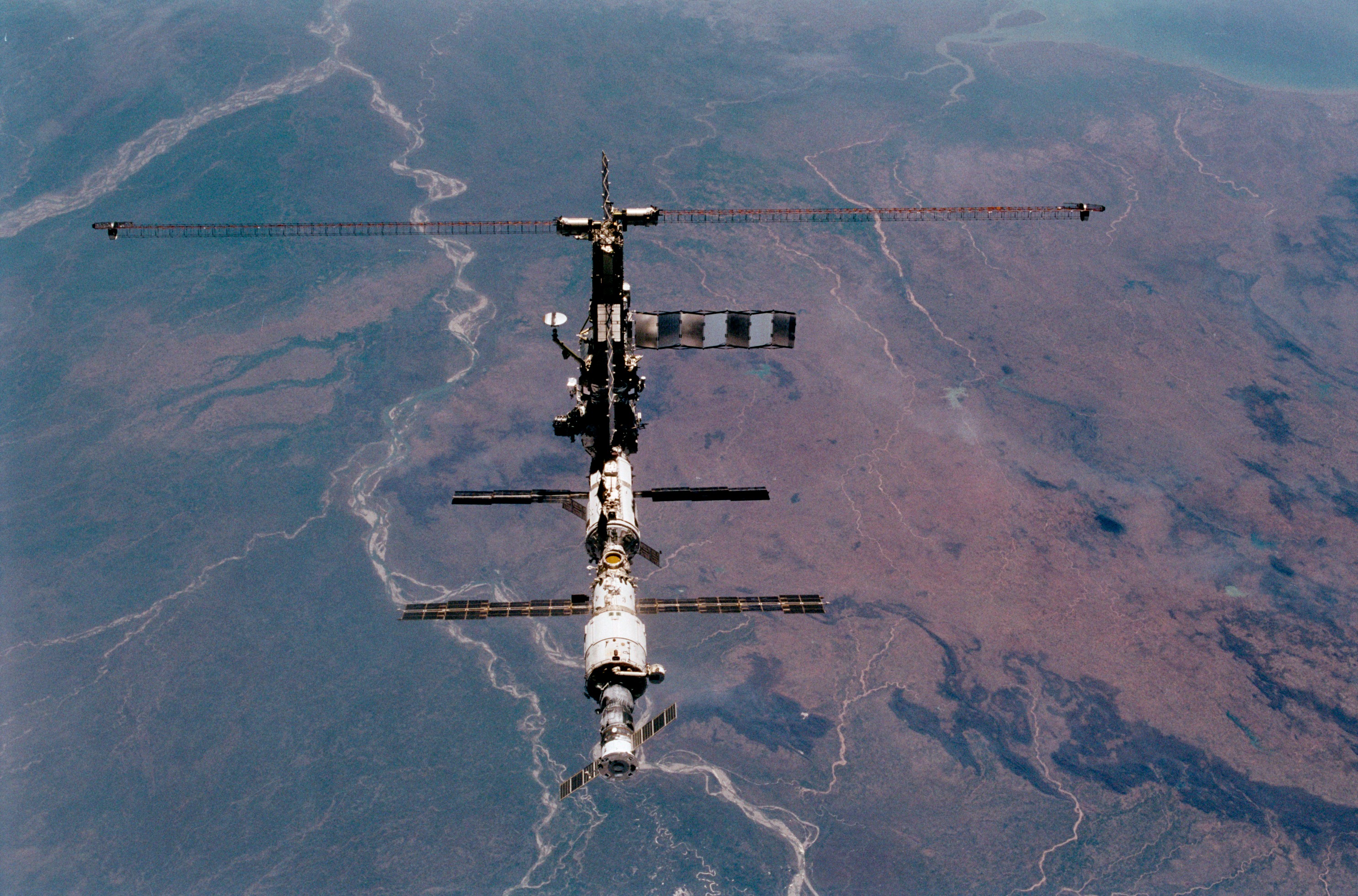
The International Space Station is a 3D statics problem built in orbit. NASA lists a mass of 419,725 kg and says the 55-foot Canadarm2 has seven joints and is used to move entire modules. On the ground and during launch, every module, joint and attachment had to be checked for 3D forces and moments, and the station’s eight solar arrays provide 75 to 90 kilowatts of clean power for its science, including Earth observation.
On Saving Planets: Intro to Aerospace Engineering
Sources: NASA: International Space Station facts and figures · Engineering Statics, Chapter 5: Rigid body equilibrium
Free learning resources
- Engineering Statics, Ch. 5 Rigid body equilibrium (3D): Free textbook chapter.
- MIT OpenCourseWare 2.001 Mechanics and Materials I: MIT notes and problems.
Unit 6 · Week 8
Trusses: Method of Joints and Method of Sections
Ideal trusses, tension and compression members, the method of joints, zero-force members, the method of sections, and truss determinacy.
Learning objectives
By the end of this unit you can:
- State the assumptions of an ideal truss.
- Find member forces by the method of joints.
- Spot zero-force members by inspection.
- Find a few member forces quickly by the method of sections.
Key concepts
- An ideal truss has straight members joined by frictionless pins and loaded only at the joints, so every member is a two-force member in tension (T) or compression (C).
- Method of joints: each joint is a particle with two equations; start at a joint with no more than two unknowns.
- Zero-force members: at an unloaded joint with two non-collinear members, both are zero; at an unloaded joint with two collinear members and a third, the third is zero.
- Method of sections: cut through no more than three members with unknown forces and use the three equations of a rigid body on one side; take moments where two cut members meet.
- A plane truss with m members, r reactions and j joints is determinate when m + r = 2j (and it is stable).
Key equations
Worked examples, step by step
Example 6.1 A triangle truss spans 4 m with its apex 2 m high at mid-span; 10 kN hangs at the apex. Find the member forces.
Show the steps
- Reactions: 5 kN at each support.
- At A: F_AC sin 45° = 5, so F_AC = 7.07 kN.
- Horizontal at A: F_AB = F_AC cos 45°.
Answer: AC and BC: 7.07 kN (C); AB: 5 kN (T).
Example 6.2 A truss is 3 m deep. At a section, the moment of the loads and reactions on the left side about the bottom joint is 60 kN·m. Find the top chord force.
Show the steps
- Moments about the bottom joint where the other two cut members meet.
- F × 3 = 60.
Answer: 20 kN (C) in the top chord.
Example 6.3 In a bridge truss, an unloaded joint joins two collinear bottom-chord members and one vertical. Find the vertical’s force.
Show the steps
- Sum forces perpendicular to the chord at that joint: only the vertical has a component.
Answer: Zero: it is a zero-force member under this loading.
Practice problems
Work each on paper first, then check.
A triangle truss spans 6 m with 30° base angles; 12 kN hangs at the apex. Find the forces.
Show answer
R = 6 kN each; F_AC = 6/sin 30° = 12 kN (C); F_AB = 12 cos 30° = 10.39 kN (T).
A plane truss has 9 members, 6 joints and 3 reactions. Is it determinate?
Show answer
m + r = 12 = 2j, so yes (if stable).
Why keep zero-force members if they carry nothing?
Show answer
They brace compression members against buckling and carry load when the loading changes.
NASA lists the ISS truss as 94 m long and the station as 109 m end to end. What fraction of the length is truss?
Show answer
94/109 = 0.86, about 86%.
Common misconceptions
Myth: Members in a truss bend.
Actually: In an ideal truss, members only stretch or shorten (pure tension or compression).
Myth: Zero-force members can be removed.
Actually: They stabilize the truss and carry load under other cases.
Myth: A negative answer means a mistake.
Actually: If you assumed tension, a negative answer means compression.
Flashcards
Ideal truss
Pinned joints, loads at joints, straight members.
Method of joints
ΣF = 0 at each joint.
Method of sections
Cut ≤ 3 members; use the rigid-body equations.
Zero-force member
Carries no load under the given loading.
m + r = 2j
Plane truss determinacy.
T and C
Tension pulls on joints; compression pushes.
Self-check quiz
How this helps save the planet
The space station’s backbone is a truss. NASA gives its truss length as 310 feet (94 meters), carrying solar arrays with a wingspan of 109 meters; the eight arrays provide 75 to 90 kilowatts. A truss gets great stiffness from little material because each member only stretches or shortens, which is also why trusses hold up bridges, transmission towers and wind-turbine lattice towers with less steel.
On Saving Planets: Intro to Aerospace Engineering
Sources: NASA: International Space Station facts and figures · Engineering Statics, Chapter 6: Equilibrium of structures
Free learning resources
- Engineering Statics, Ch. 6 Equilibrium of structures: Free textbook chapter (trusses, frames, machines).
- MIT OpenCourseWare 2.001 Mechanics and Materials I: MIT notes on trusses.
Unit 7 · Week 9
Frames and Machines
Structures with multiforce members: taking frames apart, pin forces on each member, mechanical advantage of machines, and pulley systems.
Learning objectives
By the end of this unit you can:
- Tell a frame or machine from a truss.
- Take a frame apart and apply Newton’s third law at shared pins.
- Find the output force and mechanical advantage of simple machines.
- Analyze ideal pulley systems.
Key concepts
- Frames and machines contain at least one multiforce member: a member with forces at three or more points, or with forces and moments, so it can bend.
- Take the structure apart. At each shared pin, the forces on the two members are equal and opposite.
- Find two-force members first; their force directions are known, which cuts the unknowns.
- A machine changes an input force into an output force; mechanical advantage MA = F_out/F_in (ideal, without friction).
- In an ideal pulley system the load is shared by the rope segments that support it, so effort = load/n.
Key equations
Worked examples, step by step
Example 7.1 A hand squeezes pliers with 100 N at 120 mm from the pin; the jaws grip 30 mm from the pin. Find the grip force.
Show the steps
- Moments about the pin on one handle: F_jaw × 30 = 100 × 120.
Answer: 400 N (MA = 4).
Example 7.2 A wheelbarrow load of 600 N sits 0.4 m from the wheel axle; the handles are 1.4 m from the axle. Find the lifting force.
Show the steps
- Moments about the axle: F × 1.4 = 600 × 0.4.
Answer: 171.4 N.
Example 7.3 An ideal pulley system has 4 rope segments supporting an 800 N load. Find the effort.
Show the steps
- Each segment carries the same tension T; 4T = 800.
Answer: 200 N.
Practice problems
Work each on paper first, then check.
A compound bolt cutter has stages with mechanical advantages 4 and 5. Hands push 150 N. Find the cutting force.
Show answer
Total MA = 20; F = 3,000 N.
An ideal block and tackle has 6 supporting segments under a 1,200 N load. Find the pull.
Show answer
200 N.
Why can’t you use the method of joints on a frame?
Show answer
Multiforce members carry forces that are not along the member, so joints alone do not give enough equations.
A lever is 2 m long with the pivot 0.25 m from the load. What force lifts 1,000 N?
Show answer
F × 1.75 = 1000 × 0.25, F = 142.9 N.
Common misconceptions
Myth: Every member of a frame is a two-force member.
Actually: At least one is multiforce; that is what makes it a frame.
Myth: Machines create energy.
Actually: Ideal machines trade force for distance; work in equals work out.
Myth: Pin forces act the same direction on both members.
Actually: Equal and opposite, by Newton’s third law.
Flashcards
Frame
Stationary structure with a multiforce member.
Machine
Moving parts that change a force.
Multiforce member
Forces at three or more points, or forces plus moments.
Shared pin
Equal and opposite forces on each member.
Mechanical advantage
F_out/F_in.
Ideal pulley system
Effort = load/n.
Self-check quiz
How this helps save the planet
Frames that come apart can be reused. The U.S. EPA reports that 600 million tons of construction and demolition debris were generated in the United States in 2018, with just over 455 million tons directed to next use and just under 145 million tons sent to landfills. EPA promotes salvaging and reusing building components; frames designed with bolted or pinned joints, which you analyze member by member in this unit, are easier to take apart and reuse.
On Saving Planets: Solutions
Sources: U.S. EPA: Sustainable management of construction and demolition materials · Engineering Statics, Chapter 6: Equilibrium of structures
Free learning resources
- Engineering Statics, Ch. 6 Frames and machines: Free textbook chapter.
- PhET: Balancing Act: Levers.
Unit 8 · Weeks 10–11
Centroids, Distributed Loads, Fluid Pressure and Area Moments of Inertia
Center of gravity and centroids by integration and composite parts, distributed loads, hydrostatic pressure on submerged surfaces, and area moments of inertia with the parallel-axis theorem.
Learning objectives
By the end of this unit you can:
- Find centroids of composite areas.
- Find the resultant and line of action of hydrostatic pressure on a vertical wall or gate.
- Compute area moments of inertia of rectangles and composite shapes.
- Apply the parallel-axis theorem.
Key concepts
- The center of gravity is where the total weight acts. For a uniform plate it equals the centroid of the area: x̄ = ΣxᵢAᵢ/ΣAᵢ.
- Composite parts: split a shape into rectangles, triangles and circles; holes count as negative areas.
- Water pressure grows linearly with depth, p = ρgh. On a vertical wall of width b and depth h, the resultant is ½ρgh²b, acting h/3 above the bottom.
- The area moment of inertia I = ∫y² dA measures how far area sits from an axis; it controls how stiff a beam is in bending (next course).
- Parallel-axis theorem: I = I_c + Ad², where I_c is about the centroidal axis and d the distance between axes.
Key equations
Worked examples, step by step
Example 8.1 An L-shape is a 100 × 20 mm bar along the x axis plus a 20 × 80 mm bar standing on its left end (x from 0 to 20 mm, y from 20 to 100 mm). Find the centroid.
Show the steps
- A₁ = 2000 mm² at (50, 10); A₂ = 1600 mm² at (10, 60).
- x̄ = (2000 × 50 + 1600 × 10)/3600.
- ȳ = (2000 × 10 + 1600 × 60)/3600.
Answer: (32.2, 32.2) mm.
Example 8.2 A vertical gate 2 m wide holds water 3 m deep. Find the resultant force and where it acts.
Show the steps
- F = ½ρgh²b = ½ × 1000 × 9.81 × 3² × 2.
- Line of action: h/3 above the bottom.
Answer: 88.3 kN, 1 m above the bottom (2 m below the surface).
Example 8.3 Find I for a 100 mm wide, 200 mm deep rectangle about its centroidal axis and about its base.
Show the steps
- I_c = bh³/12 = 100 × 200³/12.
- I_base = I_c + A(100)² with A = 20,000 mm².
Answer: I_c = 66.7 × 10⁶ mm⁴; I_base = 266.7 × 10⁶ mm⁴ (= bh³/3).
Practice problems
Work each on paper first, then check.
Reclamation gives the maximum water pressure at the base of Hoover Dam as 45,000 lb/ft². Convert to pascals and find the water depth that makes this pressure.
Show answer
45,000 × 47.88 = 2.15 MPa; h = p/(ρg) = 219.6 m, about 721 ft, close to the dam’s 726.4 ft height.
Find the centroid height of a semicircle of radius 0.3 m above its diameter.
Show answer
ȳ = 4r/(3π) = 0.127 m.
Where is the centroid of a triangle of height h?
Show answer
h/3 above the base.
Find I_c of a 50 × 50 mm square.
Show answer
bh³/12 = 50⁴/12 = 520,833 mm⁴ (5.21 × 10⁵ mm⁴).
Common misconceptions
Myth: The centroid is always inside the shape.
Actually: Not for an L, a C or a ring; it can sit in empty space.
Myth: Water pushes equally hard at every depth.
Actually: Pressure grows linearly with depth.
Myth: I is the same about any axis.
Actually: It grows with the square of the distance from the axis (parallel-axis theorem).
Flashcards
Centroid
Area-weighted average position.
Center of gravity
Where the total weight acts.
Hydrostatic pressure
p = ρgh.
Wall force
½ρgh²b at h/3 above the bottom.
Area moment of inertia
I = ∫y² dA; bh³/12 for a rectangle.
Parallel-axis theorem
I = I_c + Ad².
Self-check quiz
How this helps save the planet
Hoover Dam is fluid statics in concrete. The Bureau of Reclamation says the dam is 726.4 feet from foundation rock to the crest, that the maximum water pressure at its base is 45,000 pounds per square foot, and that it is a concrete arch-gravity dam in which the water load is carried by both gravity action and horizontal arch action. The practice problem shows that 45,000 lb/ft² is about what 220 m of water produces. The dam’s weight and shape keep the resultant of that pressure inside its base so it neither slides nor tips, while its reservoir feeds a hydropower plant.
On Saving Planets: Physics II
Sources: U.S. Bureau of Reclamation: Hoover Dam frequently asked questions · Engineering Statics, Chapter 7: Centroids and centers of gravity
Free learning resources
- Engineering Statics, Ch. 7 Centroids and centers of gravity: Free textbook chapter.
- Engineering Statics, Ch. 10 Moments of inertia: Free textbook chapter.
- OpenStax UP1, 9.6 Center of mass: Physics view.
- OpenStax UP1, 14.1 Fluids, density and pressure: Pressure with depth.
- PhET: Under Pressure: Interactive.
Unit 9 · Weeks 12–13
Internal Forces: Shear and Bending-Moment Diagrams, and Cables
Internal normal force, shear and bending moment, sign conventions, shear and moment diagrams from equilibrium and from the load–shear–moment relations, and cables under distributed loads.
Learning objectives
By the end of this unit you can:
- Find the internal forces at any section of a beam.
- Draw shear and bending-moment diagrams for point and distributed loads.
- Use dV/dx = −w and dM/dx = V to check diagrams.
- Find the tension in a parabolic cable.
Key concepts
- Cut a beam at x and the exposed face carries a normal force N, a shear force V and a bending moment M, found from equilibrium of either piece.
- Sign convention used here: positive shear turns a segment clockwise; positive moment bends the beam into a smile (sagging).
- Relations: dV/dx = −w (load per length, downward positive) and dM/dx = V. A point load makes a jump in V; a couple makes a jump in M.
- The maximum moment occurs where V = 0 (or at a jump in V); it is the value that sizes the beam.
- A cable under a uniform horizontal load hangs in a parabola; the horizontal tension is H = wL²/(8s) for span L and sag s, and the tension is largest at the supports.
Key equations
Worked examples, step by step
Example 9.1 A 6 m simply supported beam carries 4 kN/m. Find V(x), M(x) and the maximum moment.
Show the steps
- Reactions: 12 kN each.
- V = 12 − 4x; M = 12x − 2x².
- V = 0 at x = 3 m.
Answer: M_max = wL²/8 = 18 kN·m at mid-span.
Example 9.2 The Unit 4 beam (6 m, 12 kN at 2 m from A). Draw V and M.
Show the steps
- R_A = 8 kN, R_B = 4 kN.
- V = +8 kN for 0 < x < 2, then −4 kN.
- M rises linearly to 8 × 2 at the load, then falls to 0 at B.
Answer: M_max = 16 kN·m under the load.
Example 9.3 A cable spans 100 m with a 10 m sag and carries 2 kN/m along the span. Find the horizontal and maximum tensions.
Show the steps
- H = wL²/(8s) = 2 × 100²/80.
- Vertical at each support = wL/2 = 100 kN.
- T_max = √(250² + 100²).
Answer: H = 250 kN; T_max = 269.3 kN.
Practice problems
Work each on paper first, then check.
A 3 m cantilever has 5 kN at its tip. Give V and the maximum moment.
Show answer
V = 5 kN everywhere; |M_max| = 15 kN·m at the wall (hogging).
What are V and M at mid-span of the 6 m, 4 kN/m beam?
Show answer
V = 0, M = 18 kN·m.
If the cable’s sag is halved to 5 m, what happens to H?
Show answer
H doubles to 500 kN: flatter cables pull harder.
A 5 m simply supported beam carries 6 kN/m. Find M_max.
Show answer
6 × 25/8 = 18.75 kN·m.
Common misconceptions
Myth: Maximum moment is always at mid-span.
Actually: Only for symmetric loads; in general it is where V = 0 or V jumps.
Myth: Shear and moment diagrams have the same shape.
Actually: M is the integral of V, so it is one degree higher.
Myth: A tighter (flatter) cable feels less tension.
Actually: Less sag means more tension, H = wL²/(8s).
Flashcards
Internal forces
N, V and M at a cut.
dV/dx = −w
Load sets the slope of shear.
dM/dx = V
Shear sets the slope of moment.
M_max
Where V = 0 or jumps.
wL²/8
Maximum moment, uniform load, simple span.
Parabolic cable
H = wL²/(8s).
Self-check quiz
How this helps save the planet
Bridges have to last longer than ever. ASCE’s Report Card says that at the current replacement rate, a bridge built today will need to last 126 years, that about 45% of bridges have passed their 50-year design lives, and that trucks heavier than many bridges were designed for can overstress bridge elements. Shear and moment diagrams are how engineers check whether an older beam can still carry today’s loads, which lets good bridges be preserved instead of rebuilt.
On Saving Planets: Solutions
Sources: ASCE Report Card for America’s Infrastructure: Bridges · Engineering Statics, Chapter 8: Internal forces
Free learning resources
- Engineering Statics, Ch. 8 Internal forces: Free textbook chapter.
- MIT OpenCourseWare 2.001 Mechanics and Materials I: MIT notes on beams.
Unit 10 · Week 14
Friction
Dry (Coulomb) friction, impending motion, angle of repose, sliding versus tipping, wedges, ladders, and belt or rope friction.
Learning objectives
By the end of this unit you can:
- Decide whether a body slides, stays put or tips.
- Solve impending-motion problems with F = μ_sN.
- Use the angle of repose and the ladder problem.
- Use the belt-friction equation T₂/T₁ = e^{μβ}.
Key concepts
- Static friction adjusts to whatever is needed, up to a maximum F_max = μ_sN. Once sliding starts, kinetic friction is about μ_kN, usually a bit less.
- A block on a slope stays put if tan θ ≤ μ_s; the steepest angle, tan⁻¹ μ_s, is the angle of repose.
- Check both sliding and tipping: a tall box pushed high may tip before it slides.
- Wedges and screws use friction to hold loads; solve each piece as a rigid body with friction opposing the impending motion.
- A rope wrapped around a post through angle β (in radians) holds T₂ = T₁ e^{μβ}, so a few turns hold a large load with a small pull.
Key equations
Worked examples, step by step
Example 10.1 A 50 kg crate sits on a 20° slope with μ_s = 0.4. Does it slip?
Show the steps
- tan 20° = 0.364 < 0.4, so it holds.
- Friction needed = mg sin 20° = 167.8 N; available = 0.4 × mg cos 20° = 184.4 N.
Answer: It stays put; friction needed 167.8 N of 184.4 N available.
Example 10.2 What force parallel to the slope starts the same crate moving up?
Show the steps
- Friction now acts down the slope at its maximum.
- P = mg sin 20° + 0.4 mg cos 20°.
Answer: 352.2 N.
Example 10.3 A rope makes 1.5 turns around a post (β = 3π) with μ = 0.3. What load can a 100 N pull hold?
Show the steps
- T₂/T₁ = e^{0.3 × 3π} = e^{2.83}.
Answer: Ratio 16.9, so about 1,690 N.
Practice problems
Work each on paper first, then check.
Find the angle of repose for μ_s = 0.6.
Show answer
tan⁻¹ 0.6 = 31.0°.
A 5 m ladder weighing 200 N leans at 60° to the floor against a smooth wall. Find the smallest floor μ_s that holds it.
Show answer
Wall force N_w: N_w × 5 sin 60° = 200 × 2.5 cos 60°, N_w = 57.7 N; floor N = 200 N; μ_min = 57.7/200 = 0.289.
A box 0.5 m wide and 1.5 m tall (μ_s = 0.4) is pushed at its top edge. Does it slide or tip first?
Show answer
Slides when P > 0.4W; tips when P × 1.5 > W × 0.25, P > 0.167W. It tips first.
A rope makes 2 turns (β = 4π) with μ = 0.2. Find T₂/T₁.
Show answer
e^{0.8π} = 12.3.
Common misconceptions
Myth: Friction always equals μN.
Actually: Only at impending or actual sliding; before that it is whatever balance needs.
Myth: Friction depends on contact area.
Actually: In the simple Coulomb model it depends only on μ and N.
Myth: Friction always opposes motion, so it points down a slope.
Actually: It opposes impending relative motion; on a block about to slide down, it points up the slope.
Flashcards
Static friction
F ≤ μ_sN.
Kinetic friction
F ≈ μ_kN, usually a bit smaller.
Angle of repose
tan θ = μ_s.
Tipping check
Compare moments about the tipping edge.
Capstan equation
T₂/T₁ = e^{μβ}.
Impending motion
Friction at its maximum, opposing the motion about to happen.
Self-check quiz
How this helps save the planet
A slope stays put for the same reason a block on a ramp does: friction and strength in the soil resist the pull of gravity down the slope. The USGS Landslide Hazards Program works to reduce long-term losses from landslides by understanding the causes of ground failure, and notes that wildfire can increase landslide susceptibility in mountainous terrain. Keeping slopes planted and stable protects both people and watersheds.
On Saving Planets: Deforestation
Sources: USGS Landslide Hazards Program · Engineering Statics, Chapter 9: Friction
Free learning resources
- Engineering Statics, Ch. 9 Friction: Free textbook chapter.
- OpenStax UP1, 6.2 Friction: Physics view.
- PhET: Friction: Interactive.
- PhET: The Ramp: Forces on a slope.
The lab (Statics lab)
The lab is the hands-on part of the course. Here it is free and for practice only, with no credit.
Every lab can be done in a free PhET simulation or with cheap household items. Keep loads small (a few kilograms at most), keep feet and hands out from under hanging loads, and never stand on a test structure.
Safety reference: OSHA: Hand and power tools
Lab A: Force table and the equilibrant
Week 2
Goal: Add two forces by components, predict the single force that balances them, and test the prediction in simulation and with spring or luggage scales.
Procedure
- Open PhET Vector Addition. Make F₁ = 2.0 N at 0° and F₂ = 3.0 N at 90°, and read the resultant’s size and angle.
- Predict the equilibrant (same size, opposite direction) by components.
- Home: tie three strings to a small ring. Pull two with luggage or spring scales at 0° and 90° until they read 2.0 N and 3.0 N (about 204 g and 306 g), and measure the third string’s pull and angle with a phone protractor.
- Repeat with F₂ at 60° and compare.
Data table
| Force | Size (N) | Angle (°) |
|---|---|---|
| F₁ | 2.00 | 0 |
| F₂ | 3.00 | 90 |
| Resultant | 3.61 | 56.3 |
| Equilibrant | 3.61 | 236.3 |
Values computed by components for the forces chosen (sample values); home readings usually agree within a few percent.
Sample calculation
- R = √(2² + 3²) = 3.61 N at tan⁻¹(3/2) = 56.3°.
- The equilibrant points the other way: 56.3° + 180° = 236.3°.
- With F₂ at 60°: R = (3.5, 2.60) N, size 4.36 N at 36.6°.
Safety
- Keep strings short and pulls gentle; a snapping string can flick into eyes.
Home or virtual alternative
- The ring-and-scales step is the home version; a kitchen scale and string over a chair back also works.
Planet link: Engineers balance wind loads on turbine blades and towers by exactly this kind of vector addition. U.S. DOE: How do wind turbines work?
Lab B: Cable tension and sling angle
Week 3
Goal: Measure how the tension in two symmetric strings holding a weight grows as the strings get flatter, and compare with T = W/(2 sin θ).
Procedure
- Hang a 1.0 kg mass (a 1 L water bottle) from the middle of a string; tie each end to a luggage scale held by a helper or clipped to two chair backs.
- Move the supports to set string angles of about 90°, 60°, 45°, 30° and 15° from horizontal (use a phone protractor).
- Record both scale readings at each angle and average them.
- Plot T against 1/sin θ; the slope should be W/2 = 4.9 N.
Data table
| θ from horizontal (°) | T (N) for 9.81 N |
|---|---|
| 90 | 4.91 |
| 60 | 5.66 |
| 45 | 6.94 |
| 30 | 9.81 |
| 15 | 18.95 |
Values computed from T = W/(2 sin θ) for a 1.0 kg mass.
Sample calculation
- At 30° each string carries the full weight, 9.81 N.
- At 15° each carries almost twice the weight: 18.95 N.
- Slope of T against 1/sin θ = W/2 = 4.91 N.
Safety
- Keep the mass low over a soft surface and keep feet out from under it.
- Use only a light mass; at small angles the string tension gets large.
Home or virtual alternative
- The whole lab is a home lab; two kitchen-scale readings with a string over a smooth rod also work.
PhET: Forces and Motion: Basics
Planet link: Mooring lines on floating offshore wind platforms are sized with the same geometry: shallow line angles mean high tension. U.S. DOE: Floating Offshore Wind Shot
Lab C: Moments and an unknown mass on a balance
Week 5
Goal: Use ΣM = 0 on a ruler balance to find an unknown mass, and test balance rules in PhET.
Procedure
- In PhET Balancing Act, balance a known brick against a mystery object and compute its mass from the distances.
- Home: balance a 30 cm ruler on a pencil at its 15 cm mark.
- Place a known 20 g stack of coins (weigh it on a kitchen scale) at 4, 6 and 8 cm from the pivot and slide the unknown object until the ruler balances; record its distance each time.
- Compute the unknown mass from each trial and average.
Data table
| Known 20 g at (cm) | Unknown balances at (cm) |
|---|---|
| 4.0 | 6.4 |
| 6.0 | 9.6 |
| 8.0 | 12.8 |
Sample values for a 12.5 g unknown.
Sample calculation
- m = 20 × 4.0/6.4 = 12.5 g, and every row gives the same value.
- The ratio of distances is constant (1.6), which is the inverse ratio of the masses.
Safety
- None beyond keeping small coins away from young children.
Home or virtual alternative
- The ruler-and-coins step is the home version.
Planet link: The same moment balance sets how big a wind turbine’s foundation must be to resist the wind’s overturning moment. U.S. DOE: How do wind turbines work?
Lab D: Build and analyze a small truss
Week 8
Goal: Build a triangle truss from craft sticks, predict member forces by the method of joints, and see which members are in tension and compression.
Procedure
- Glue craft sticks into a triangle 30 cm across and 10 cm high (base angle 33.7°).
- Rest it on two books and hang 5, 10 and 20 N (0.5, 1 and 2 L water bottles) from the apex.
- Compute the member forces by the method of joints for each load.
- Replace the bottom member with string: it stays taut (tension). Try the same with a sloped member and see it fold (compression).
Data table
| Load P (N) | Sloped members (N, C) | Bottom member (N, T) |
|---|---|---|
| 5 | 4.51 | 3.75 |
| 10 | 9.01 | 7.50 |
| 20 | 18.0 | 15.0 |
Values computed for the 30 cm × 10 cm geometry (sample values).
Sample calculation
- θ = tan⁻¹(10/15) = 33.7°.
- At 10 N: F_AC = 5/sin 33.7° = 9.01 N (C); F_AB = 9.01 cos 33.7° = 7.50 N (T).
- Member forces scale linearly with the load.
Safety
- Hot glue burns; let joints cool.
- Keep hands and feet out from under hanging bottles.
Home or virtual alternative
- The whole lab is a home lab; stiff card strips and tape also work.
Engineering Statics: interactive truss examples
Planet link: The space station’s 94 m truss and every lattice wind or power-line tower carry loads through members in tension and compression like these. NASA: International Space Station facts and figures
Lab E: Finding a centroid with a plumb line
Week 10
Goal: Find the centroid of a cardboard L-shape by hanging it from two points, and compare with the composite-area calculation.
Procedure
- Cut an L from cardboard: a 20 × 4 cm bar along the bottom and a 4 × 16 cm bar standing on its left end.
- Push a pin near one corner, let the shape and a plumb line hang freely, and draw the plumb line on the card.
- Repeat from a second corner. The lines cross at the centroid; measure its x and y from the bottom-left corner.
- Compute the centroid from the two rectangles and compare.
Data table
| Part | Area (cm²) | x̃ (cm) | ỹ (cm) |
|---|---|---|---|
| Bottom bar | 80 | 10 | 2 |
| Upright bar | 64 | 2 | 12 |
| L-shape | 144 | 6.44 | 6.44 |
Values computed for the stated dimensions; your plumb-line crossing should land within a few millimeters.
Sample calculation
- x̄ = (80 × 10 + 64 × 2)/144 = 6.44 cm.
- ȳ = (80 × 2 + 64 × 12)/144 = 6.44 cm.
- The centroid lies outside the cardboard, in the empty corner region, which the plumb lines confirm.
Safety
- Cut away from your hand; use a cutting mat.
Home or virtual alternative
- The whole lab is a home lab.
Engineering Statics, Chapter 7: centroids
Planet link: A gravity dam must keep the resultant of its weight and water pressure inside its base; locating centroids is the first step. U.S. Bureau of Reclamation: Hoover Dam frequently asked questions
Lab F: Measuring friction on a slope and around a post
Week 14
Goal: Measure the static friction coefficient from the slip angle of a box on a tilted book, and measure how a rope’s holding power grows with wraps around a mug.
Procedure
- Put a small box on a hardcover book and tilt the book slowly; read the slip angle with a phone inclinometer. Repeat three times.
- Compute μ_s = tan θ for each trial and average.
- Wrap string 0.5, 1 and 1.5 turns around a smooth mug. Hang a small weight on one end and measure the pull needed on the other to just hold it with a luggage scale.
- Compare the ratio with e^{μβ}, β = 2π × turns, using μ found from one trial.
Data table
| Trial or turns | Reading | Result |
|---|---|---|
| Trial 1 | 22° | μ_s = 0.404 |
| Trial 2 | 24° | μ_s = 0.445 |
| Trial 3 | 23° | μ_s = 0.424 |
| 0.5 turn, μ = 0.25 | — | ratio 2.19 |
| 1 turn | — | ratio 4.81 |
| 1.5 turns | — | ratio 10.55 |
Sample values; your angles depend on the box and book surfaces, and the string-on-mug μ of 0.25 is a sample value.
Sample calculation
- Mean μ_s = (0.404 + 0.445 + 0.424)/3 = 0.424.
- Each extra half turn multiplies the holding ratio by e^{0.25π} = 2.19.
- One full turn: e^{0.5π} = 4.81.
Safety
- Use a light weight and keep it over a soft surface.
Home or virtual alternative
- The whole lab is a home lab.
PhET: Friction · PhET: The Ramp
Planet link: The slip-angle idea is the starting point for judging slope stability, which the USGS studies to reduce landslide losses. USGS Landslide Hazards Program
Exam prep practice sets
Time yourself: about 10 minutes per problem. Then compare with the full solutions.
Midterm practice set (Units 1–5)
Find the resultant of 400 N along +x and 300 N along +y.
Show full solution
- R = √(400² + 300²); θ = tan⁻¹(300/400).
Answer: 500 N at 36.9°.
An 80 kg mass hangs from two cables, each 40° above horizontal. Find the tension.
Show full solution
- 2T sin 40° = 784.8 N.
Answer: 610.5 N.
F = (0, −250) N acts at (3, 2) m. Find its moment about the origin.
Show full solution
- M_z = xF_y − yF_x = 3(−250) − 0.
Answer: −750 N·m (750 N·m clockwise).
A 5 m simply supported beam carries 10 kN at 1.5 m from A. Find the reactions.
Show full solution
- ΣM_A: 5R_B = 10 × 1.5.
Answer: R_B = 3 kN, R_A = 7 kN.
A 2 m cantilever carries 3 kN/m. Find the wall reactions.
Show full solution
- Resultant 6 kN at 1 m.
Answer: V = 6 kN, M = 6 kN·m.
Final practice set (all units)
A triangle truss spans 8 m with its apex 3 m high at mid-span; 20 kN hangs at the apex. Find the member forces.
Show full solution
- R = 10 kN each; sin θ = 0.6, cos θ = 0.8.
- F_AC = 10/0.6; F_AB = F_AC × 0.8.
Answer: Sloped members 16.67 kN (C); bottom 13.33 kN (T).
A T-section has a 120 × 20 mm flange on top of a 20 × 100 mm web. Find the centroid height from the bottom.
Show full solution
- Web: 2000 mm² at 50 mm; flange: 2400 mm² at 110 mm.
Answer: 82.7 mm.
A vertical gate 3 m wide holds water 4 m deep. Find the resultant and its height above the bottom.
Show full solution
- F = ½ρgh²b.
Answer: 235.4 kN at 1.33 m above the bottom.
An 8 m simply supported beam carries 5 kN/m. Find the reactions and the maximum moment.
Show full solution
- R = wL/2; M = wL²/8.
Answer: 20 kN each; 40 kN·m.
A 30 kg crate sits on a 25° slope with μ_s = 0.5. Does it slip?
Show full solution
- tan 25° = 0.466 < 0.5.
- Needed mg sin 25° vs available 0.5 mg cos 25°.
Answer: No: 124.4 N needed, 133.4 N available.
A rope makes 2 turns around a post with μ = 0.2. Find the holding ratio.
Show full solution
- T₂/T₁ = e^{0.2 × 4π}.
Answer: 12.3.
Formula sheet
Constants
| Constant | Value |
|---|---|
| Standard acceleration of gravity, g | 9.80665 m/s² (we use 9.81 m/s²) |
| Weight of 1 kg at standard gravity | 9.81 N |
| Density of fresh water (round value used here) | 1000 kg/m³ |
| Specific weight of water, ρg | 9.81 kN/m³ |
| 1 foot | 0.3048 m (exact) |
| 1 pound-force | 4.448 N |
| 1 pound per square foot | 47.88 Pa |
Free texts and simulations
Use these free textbooks, lectures and simulations alongside the course.
- Engineering Statics: Open and Interactive (Baker and Haynes): Free, complete interactive statics textbook.
- MIT OpenCourseWare 2.001 Mechanics and Materials I: Free MIT lecture notes and problem sets.
- OpenStax University Physics Volume 1, Chapter 12: Static equilibrium: Free physics view of equilibrium.
- PhET: Vector Addition: Add and resolve vectors.
- PhET: Balancing Act: Moments and balance.
- PhET: Under Pressure: Fluid pressure with depth.
Glossary
- Angle of repose
- Steepest slope angle at which a body stays put, tan⁻¹ μ_s.
- Bending moment
- Internal moment at a beam section.
- Centroid
- Geometric center of an area or volume.
- Couple
- Two equal, opposite, parallel forces; a pure moment.
- Equilibrant
- The force that balances a set of forces.
- Fixed support
- Support that prevents translation and rotation.
- Frame
- Structure with at least one multiforce member.
- Free-body diagram
- Sketch of a body isolated with every external force on it.
- Mechanical advantage
- Output force divided by input force.
- Method of joints
- Truss analysis with ΣF = 0 at each joint.
- Method of sections
- Truss analysis with rigid-body equilibrium of a cut piece.
- Moment
- Turning effect of a force, r × F.
- Parallel-axis theorem
- I = I_c + Ad².
- Pin support
- Support that prevents translation but allows rotation.
- Resultant
- Single force equivalent to a set of forces.
- Roller support
- Support that gives one force normal to its surface.
- Shear force
- Internal force across a beam section.
- Statically indeterminate
- More unknowns than equilibrium equations.
- Truss
- Structure of two-force members pinned at joints.
- Two-force member
- Member loaded at two points only; forces lie along the line between them.
- Zero-force member
- Truss member carrying no force under a given loading.
Self-assessment rubric
No grade or credit is given. Use this to judge honestly where you are in each unit.
| Level | What it looks like |
|---|---|
| 4 · Mastery | Draws complete free-body diagrams, chooses axes and moment points well, checks determinacy, and verifies answers with an unused equation. |
| 3 · Proficient | Solves the practice problems with occasional sign or unit slips. |
| 2 · Developing | Follows worked examples but misses forces on free-body diagrams or picks moment points that leave too many unknowns. |
| 1 · Beginning | Plugs numbers into formulas without a free-body diagram; needs to revisit the unit. |
Suggested weighting if you want a score
| Part | Weight |
|---|---|
| Practice problems | 25% |
| Labs | 20% |
| Midterm practice set | 25% |
| Final practice set | 30% |
Aim for level 3 or better in every unit before moving to the next course.